Supporting guidance for Rural Sustainable Drainage Systems – Swales
This is an old version of the page
Date published: 30 March, 2015
Date superseded: 20 January, 2017
Swales are shallow grass-lined channels designed to collect water and move it gradually away downslope. Infiltration can take place along their route and the grass helps to filter out suspended sediments as well as taking up nutrients. The storage capacity can be increased and the rate of flow slowed by the construction of check dams.
Unlike ditches, they are normally dry outwith wet weather and their sides and base are grassed. The grass needs to be kept to a height of approximately 100 millimetres – you can do this by mowing, strimming or light grazing.
What are the benefits of using swales?
Swales effective at improving water quality and are:
- cheaper to construct than piped systems
- able to be incorporated into the landscape
- a low-maintenance option
- visible in operation
What makes a good swale?
- the longer the swale the better. A longer swale gives more time for the entrapment or settlement of suspended solids. A length of more than 70 metres is optimal
- there should be no sharp bends – they should curve gently
- gradients should be shallow, ideally no more than five degrees. Swales can be built on steeper ground if they are constructed so that they curve to and fro across the slope with a shallow gradient
- the sides should be sloping with a gradient no steeper than 1:3. If the swale is going to be too wide you can reduce the width by creating shallow slopes at the bottom and steepening them as you go upwards. Keep the slopes safe though
- an established grass sward is beneficial so the swale should be designed to prevent standing water
Where should the swale be located?
The location of the swale will depend on the layout of the site and the available space. Ideally the swale should run either parallel with or at right angles to the areas from where water is being collected, with hard-standing areas draining towards the swale.
On large sites, subsidiary swales may link with a main swale off to one side. Roof water may be led to swales via clean surface drains or smaller swales.
In regards to steadings, swales are useful for accepting and treating run-off from clean yard areas, preferably as part of a treatment train approach where the swale accepts run-off and then discharges to another feature such as a pond or swale or to a grassed area for further treatment. They are not appropriate for accepting more contaminated types of run-off such as slurry. They can however be used to convey lightly contaminated run-off to a constructed farm wetland.
Swales can also be used infield as part of soil erosion risk management. For example along a natural wet weather drainage line in arable fields to help stabilise soils and provide a flow pathway. They could also be used to capture down slope run-off along field boundaries or used alongside farm tracks / roads or hard standings.
Using a combination of rural sustainable drainage systems will be more effective than individual measures – the treatment train approach.
What needs to be done?
Note: Where an assessment has been carried out as part of the diffuse pollution audit there is no need to carry out the assessments noted below.
Drainage from a steading
Where it is proposed that the swale will take drainage from a steading the first step should be to carry out a drainage assessment. The aim of this is to illustrate which parts of the yard areas will be suitable to be discharged to the swale. See the annex below for information on identifying different drainage types.
Field run-off
For arable situations, the principle aim of the swale will be to collect overland run-off to allow sediment to drop out and prevent further erosion.
In grassland situations the purpose may be to capture run-off from a track or road used by livestock or machinery and to discharge it to grassland away from watercourses.
For in-field swales it will be necessary to carry out a simple risk assessment to determine where the swale should be created to be most effective.
Using a map, such as a copy of the IACS map, identify all watercourses on the farm or area of land in question.
The next step is to consider where the potential for soil erosion is greatest and where this can pose a risk to the water environment.
This assessment should consider the following:
- proximity to nearby watercourses – the closer the area is to a watercourse, the greater will be the risk
- slope of the land will be one of the most significant factors – the steeper the downward slope towards the watercourse the greater will be the risk. Slopes of over three degrees (1 in 14) should be considered moderate risk and those above eight degrees (1 in 7) considered high risk. Fields with slopes which tend to converge or fall to a specific low point or corner of the field near to a watercourse will have a particular high risk of causing pollution. Long, uninterrupted slopes are also of greater risk of erosion
- past experience – consider where it has previously been noted that surface run-off has entered a watercourse or where soil erosion has occurred.
- soil texture – light soils with a high sand content are at greater risk of erosion
Once the assessment has been completed, identify on the map those areas which are at risk of soil erosion and which may potentially pollute a watercourse. Mark on the map where the swale would be best located to intercept the run-off and where it should discharge to.
How do I size and design a swale?
The size of the area draining to the swale determines the size and design. This is the area of lightly contaminated hard standing and roof run-off that drains to the swale.
The treatment volume (Vt) is calculated by multiplying the area draining to the swale by 12 millimetres. The 12 millimetres figure represents the first flush of rain that will generally wash any light contamination from the surface. Any further rain during the same rainfall event is likely to run clean and this additional run-off will generally overflow downhill.
The gradient of the slope is then used to calculate how many check dams are required and then their spacing and sizes are calculated.
The table below shows a worked example.
| Step | Worked data example |
|---|---|
| 1 Measure the roof and hard standing areas | 5450 m2 |
| 2 Work out the swale length available on site | 120 m |
| 3 Measure the gradient along the line of the swale (see Swale Note 1 for how to do this, or use a inclinometer) | 2% |
| 4 Calculate the Treatment Volume, Vt | 5450 x 0.012 = 65.4 m3 |
| 5a Calculate the number of check dams from Swale Table A; look up the distance between check dams for the gradient determined in Step 3 | 25 m |
| 5b Divide the Swale Length from Step 2 by the distance between check dams from Step 5a to work out how many are needed | 120 ÷ 25 = 4.8 = 5 (Round your answer up to the nearest whole number) |
| 6a Calculate the volume of the check dams from Swale Table B; look up the volume held by each check dam. Initially assume a swale floor width of 1 metre. | 10 m3 |
| 6b Multiply the volume per check dam (Step 6a) by the number of check dams (Step 5b) | 10 x 5 = 50 m3 |
| 7 Ensure that the volume of all the check dams will contain the Treatment Volume, Vt | Volume held = 50 m3 but Vt = 65.4 m3 – volume insufficient |
| 8 If the volume is insufficient, repeat Step 6 and Step 7 using a greater floor width | Floor width = 1. 5m Single check dam = 13.1 m3 Volume held = (5 x 13.1) = 65.5m3 this is OK |
| Swale Table A – Distance between check dams | |||||
|---|---|---|---|---|---|
| Swale gradient (%) | 1 | 2 | 3 | 4 | 5 |
| Distance between dams (metres) | 50 | 25 | 16.5 | 12.5 | 10 |
| Swale Table B – Volume per check dam | ||||||
|---|---|---|---|---|---|---|
| Swale gradient % | ||||||
| 1 | 2 | 3 | 4 | 5 | ||
| Floor width (metres) | 1 | 20.0 | 10.0 | 6.7 | 5.0 | 4.0 |
| 1.5 | 26.3 | 13.1 | 8.8 | 6.6 | 5.3 | |
| 2.0 | 32.5 | 16.3 | 10.8 | 8.1 | 6.5 | |
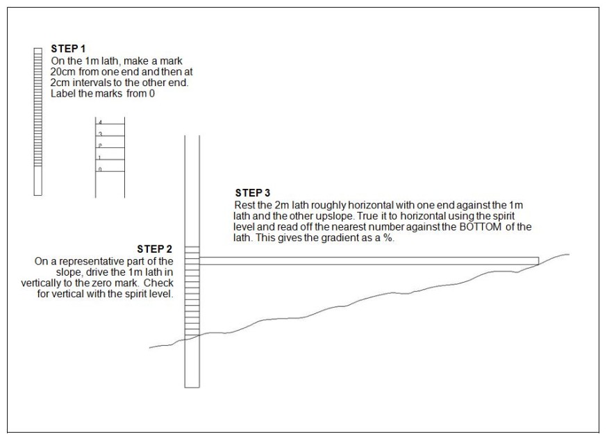
Swale Note 1 - Measuring gradients without needing a survey
You will need:
- two sturdy wooden laths, one 2 metres long and one 1 metre long
- a spirit level

How do I build a swale?
First excavate the line of the swale
- excavate the swale to a depth of 750 millimetres. Store the topsoil separately
- make the width of the swale floor equal to the width calculated. Where possible make the side slopes no steeper than a 1:3 slope – use a shallower slope if space permits
- excavate the floor of the swale a further 150–250 millimetres and fill the resulting trench with some of the retained topsoil
Now build the check dams
- excavate a trench across the swale 200 millimetres deep and 3.3 metres long
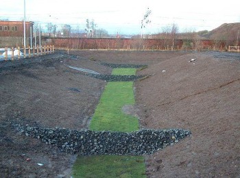
- at the lower end of each trench, build up the check dam from the 75–150 millimetres grade broken stone to a height of 500 millimetres above the floor of the swale. The sides of the check dam should have a 1:2 slope

Swale with check dams – © Chris Jefferies / University of Abertay
To finish the swale
- spread the remaining topsoil over the sides of the swale and apply fertiliser and / or lime as appropriate to bring the nutrient content and pH to a standard to enable the grass to establish quickly
- grass the swale with a mixture that requires little maintenance and provide a dense, well-knit sward. For instance, a mixture of 70 per cent creeping red fescue, 20 per cent smooth-stalked meadow grass and 10 per cent creeping bent. Apply the grass mixture at about 24 grams per square metre or 240kg per hectare
Maintenance
- ideally exclude livestock where practical
- avoid compaction
- remove silt as required
- seasonal grass cutting and removal
- checking / clearing and inlets or outlets

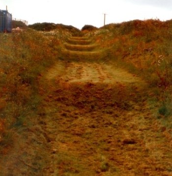
Stepped swale – © Chris Jefferies / University of Abertay
Further information
- The SuDS Manual CIRIA Report C697, CIRIA (2007)
- Guidance for Treating Lightly Contaminated Surface Run-off from Pig and Poultry Units, Northern Ireland Environment Agency (2006)
- Diffuse Pollution, Campbell et al (2004), IWA Publishing, ISBN: 1 900222 53 1
- Sedimentation in Small Constructed Wetlands. Retention of Particles, Phosphorus and Nitrogen in Streams from Arable Watersheds, Braskerud BC (2001), Doctor Scientiarum Theses 2001:10, Agricultural University of Norway, As, Norway, ISSN: 0802-3220
- Best Management Practice (BMPs) Manual
Annex – Identifying run-off types
In general, farm steadings, particularly livestock farms, produce a wide range of run-off ranging from relatively clean roof water to highly contaminated run-off and slurry.
Roof run-off can be considered relatively clean and may already directly discharge to a watercourse. Exceptions may include poultry or pig house roofs with roof vents. Also, any buildings or areas constructed after 1 April, 2007 must be drained by a sustainable drainage system, and roof water can discharge to a closed soakaway or to a watercourse via an infiltration trench or swale.
Yard run-off tends to vary to a greater degree in its polluting load. Therefore, for the purpose of producing the plan for this option, run-off should be classified as:
Slurry
The Control of Pollution (Silage, Slurry and Agricultural Fuel Oil) (Scotland) Regulations 2003 as amended (SSAFO) defines slurry as excreta produced by livestock while in a yard or building and includes a mixture of run-off containing excreta, bedding etc, from yards and buildings used by livestock and middens, weeping wall structures etc.
Run-off from such areas requires to be collected in a slurry storage system. However there is a provision to allow certain types of slurry to be conveyed to a constructed farm wetland that has been designed in accordance with the Constructed Farm Wetland Design Manual. The types of slurry that can be conveyed to such constructed farm wetlands for treatment includes run-off from:
- areas used by livestock occasionally, but excluding areas where livestock regularly move on and off to be milked, housed, fed or gathered
- silos within the period 1 November to 30 April, unless a crop has been added to the silo within this period. This excludes run-off from silos where livestock have access, such as self-feed silos
Lightly contaminated run-off
This could include drainage from yards and areas where livestock do not frequently have access, which are not contaminated with oils and pesticides. It is accepted that such areas will build up a degree of contamination from passing machinery and other activities carried on nearby. In the majority of cases this run-off would be suitable for treatment via a rural sustainable drainage system or alternatively could discharge to local grassed areas.
Dairy washings
This includes washings from the milking parlour and rinsings from the milk storage tank(s), milking machine and ancillary equipment. These types of effluent can be highly polluting and should be collected in a slurry storage facility or a dedicated storage tank.
Pesticide contaminated run-off
Drainage from pesticide handling and loading areas must not be allowed to discharge into a surface water drainage system or a rural sustainable drainage system. There is a capital item available for upgrading pesticide handling facilities.
